#microchip
I use three main tags on this blog:
-
hypertext: linking, the Web, the future of it all.
-
garage: art and creation, tinkering, zines and books, kind of a junk drawer - sorry!
-
elementary: schooling for young kids.


#microchip
I use three main tags on this blog:
hypertext: linking, the Web, the future of it all.
garage: art and creation, tinkering, zines and books, kind of a junk drawer - sorry!
elementary: schooling for young kids.

Great idea—using the ESP8266 to hook NTP up to your table clock. I know they sell these, but this is still a great learning project. Would love to see this in Lua or JS for NodeMCU.
This post accepts webmentions. Do you have the URL to your post?
You may also leave an anonymous comment. All comments are moderated.
First time I’ve seen something like this — a simplified Arduino project to simulate the 302 neurons of a certain worm’s brain. Also led me to the Open Connectome Project — can you imagine loading a ROM of a mouse brain onto a device?
This post accepts webmentions. Do you have the URL to your post?
You may also leave an anonymous comment. All comments are moderated.
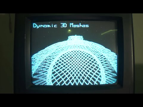
The brick phone brought into this century! While the hardware design is definitely impressive, the software looks good, too. To come up with a nice UI for a 96x64 pixel screen is something of an accomplishment.
This post accepts webmentions. Do you have the URL to your post?
You may also leave an anonymous comment. All comments are moderated.
Oh man this hack is a thrill. This guy does great stuff! Check out the VHF on an ATtiny85, too.
This post accepts webmentions. Do you have the URL to your post?
You may also leave an anonymous comment. All comments are moderated.
Complete code and build instructions for a glowing pear-shaped night light. The discovery of this cheap, translucent enclosure is a boon. I am definitely going to build this project with the fourth- and fifth-graders.
This post accepts webmentions. Do you have the URL to your post?
You may also leave an anonymous comment. All comments are moderated.

While trying to get JoyLabz Makey Makey 1.2 to work with an iPad, I discovered there is no way to reprogram it.
It seems like this information hasn’t been disclosed quite enough as it should: Makey Makey’s version 1.2, produced by JoyLabz, cannot be reprogrammed with the Arduino software. In previous versions, you could customize the firmware — remap the keys, access the AVR chip directly — using an Arduino sketch.
🙌 NOTE: Dedokta on Reddit demonstrates how to make a Makey Makey.
Now, this isn’t necessarily bad: version 1.2 has a very nice way to remap the keys. This page here. You use alligator clips to connect the up and down arrows of the Makey Makey, as well as the left and right arrows, then plug it into the USB port. The remapping page then communicates with the Makey Makey through keyboard events. (See Communication.js.)
This is all very neat, but it might be nice to see warnings on firmware projects like this one that they only support pre-1.2 versions of the Makey Makey. (I realize the page refers to “Sparkfun’s version” but it might not be clear that there are two Makey Makeys floating about—it wasn’t to me.)
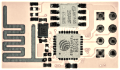
⛺ UPDATE: The text on the chip of the version 1.2 appears to read: PIC18F25K50. That would be this.
Now, how I came upon this problem was while experimenting with connecting the Makey Makey to an iPad. Instructions for doing this with the pre-1.2 Makey Makey are here in the forums—by one of the creators of the MM.
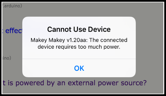
With the 1.2 version, it appears that the power draw is too great. I received this message with both an iPad Air and an original iPad Mini.
Obviously a Makey Makey isn’t quite as interesting with an iPad — but I was messing with potentially communicating through a custom app.
Anyway, without being able to recompile the firmware, the iPad seems no longer an option. (The forum post should note this as well, no?)
If you do end up trying to get a pre-1.2 Makey Makey working with the latest Arduino, I ran into many problems just getting the settings right. The github repos for the various Makey Makey firmwares are quite dated.
One of the first problems is getting boards.txt to find my avr compiler. I had this problem both on Linux and Windows. Here’s my boards.txt that finally clicked for me:
############################################################################
menu.cpu=Processor
############################################################################
################################ Makey Makey ###############################
############################################################################
makeymakey.name=SparkFun Makey Makey
makeymakey.build.board=AVR_MAKEYMAKEY
makeymakey.build.vid.0=0x1B4F
makeymakey.build.pid.0=0x2B74
makeymakey.build.vid.1=0x1B4F
makeymakey.build.pid.1=0x2B75
makeymakey.upload.tool=avrdude
makeymakey.upload.protocol=avr109
makeymakey.upload.maximum_size=28672
makeymakey.upload.speed=57600
makeymakey.upload.disable_flushing=true
makeymakey.upload.use_1200bps_touch=true
makeymakey.upload.wait_for_upload_port=true
makeymakey.bootloader.low_fuses=0xFF
makeymakey.bootloader.high_fuses=0xD8
makeymakey.bootloader.extended_fuses=0xF8
makeymakey.bootloader.file=caterina/Caterina-makeymakey.hex
makeymakey.bootloader.unlock_bits=0x3F
makeymakey.bootloader.lock_bits=0x2F
makeymakey.bootloader.tool=avrdude
makeymakey.build.mcu=atmega32u4
makeymakey.build.f_cpu=16000000L
makeymakey.build.vid=0x1B4F
makeymakey.build.pid=0x2B75
makeymakey.build.usb_product="SparkFun Makey Makey"
makeymakey.build.core=arduino
makeymakey.build.variant=MaKeyMaKey
makeymakey.build.extra_flags={build.usb_flags}
I also ended up copying the main Arduino platform.txt straight over.
Debugging this was difficult: arduino-builder was crashing (“panic: invalid memory address”) in create_build_options_map.go. This turned out to be a misspelled “arudino” in boards.txt. I later got null pointer exceptions coming from SerialUploader.java:78 — this was also due to using “arduino:avrdude” instead of just “avrdude” in platforms.txt.
I really need to start taking a look at using Ino to work with sketches instead of the Arduino software.
This post accepts webmentions. Do you have the URL to your post?
You may also leave an anonymous comment. All comments are moderated.
Sometimes your PWM pin is tied up doing SPI. You can still salvage the PWM timer itself, though.
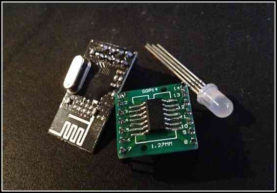
Right now the spotlight is stolen by lovely chips like the ESP8266 and the BCM2835 (the chip powering the new Raspberry Pi Zero). However, personally, I still find myself spending a lot of time with the ATtiny44a. With 14 pins, it’s not as restrictive as the ATtiny85. Yet it’s still just a sliver of a chip. (And I confess to being a sucker for its numbering.)
My current project involves an RF circuit (the nRF24l01+) and an RGB LED. But the LED needed some of the same pins that the RF module needs. Can I use this chip?
The LED is controlled using PWM — pulse-width modulation — a technique for creating an analog signal from code. PWM creates a wave — a rise and a fall.
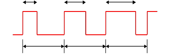
This involves a hardware timer — you toggle a few settings in the chip and it begins counting. When the timer crosses a certain threshold, it can cut the voltage. Change the threshold (the OCR) and you change the length of the wave. So, basically, if I set the OCR longer, I can get a higher voltage. If I set a lower OCR, I get a lower voltage.
I can have the PWM send voltage to the green pin on my RGB LED. And that pin can be either up at 3V (from the two AA batteries powering the ATtiny44a) or it can be down at zero — or PWM can do about anything in between.
My problem, though, was that the SPI pins — which I use to communicate with the RF chip — overlap my second set of PWM pins.
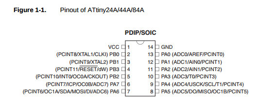
You see — pin 7 has multiple roles. It can be OC1A and it can also be DI. I’m already using its DI mode to communicate with the RF module. The OC1B pin is similarly tied up acting as DO.
I’m already using OC0A and OC0B for my green and blue pins. These pins correspond to TIMER0 — the 8-bit timer used to control those two PWM channels on OC0A and OC0B. To get this timer working, I followed a few steps:
// LED pins
#define  RED_PIN   PA0
#define  GREEN_PIN PB2
#define  BLUE_PIN  PA7
Okay, here are the three pins I want to use. PB2 and PA7 are the TIMER0 pins I was just talking about. I’m going to use another one of the free pins (PA0) for the red pin if I can.
DDRA |= (1<<RED_PIN) | (1<<BLUE_PIN);
DDRB |= (1<<GREEN_PIN);
Obviously I need these pins to be outputs — they are going to be sending out this PWM wave. This code informs the Data Direction Register (DDR) that these pins are outputs. DDRA for PA0 and PA7. DDRB for PB2.
// Configure timer0 for fast PWM on PB2 and PA7.
TCCR0A = 3<<COM0A0 | 3<<COM0B0 // set on compare match, clear at BOTTOM
       | 3<<WGM00; // mode 3: TOP is 0xFF, update at BOTTOM, overflow at MAX
TCCR0B = 0<<WGM02 | 3<<CS00; // Prescaler 0 /64
Alright. Yeah, so these are TIMER0’s PWM settings. We’re turning on mode 3 (fast PWM) and setting the frequency (the line about the prescaler.) I’m not going to go into any detail here. Suffice to say: it’s on.
// Set the green pin to 30% or so.
OCR0A = 0x1F;
// Set the blue pin to almost the max.
OCR0B = 0xFC;
And now I can just use OCR0A and OCR0B to the analog levels I need.
Most of these AVR chips have multiple timers and the ATtiny44a is no different — TIMER1 is a 16-bit timer with hardware PWM. Somehow I need to use this second timer to power th PWM on my red pin.
I could use software to kind of emulate what the hardware PWM does. Like using delays or something like that. The Make: AVR Programming book mentions using a timer’s interrupt to handcraft a hardware-based PWM.
This is problematic with a 16-bit timer, though. An 8-bit timer maxes out at 255. But a 16-bit timer maxes out at 65535. So it’ll take too long for the timer to overflow. I could lower the prescaler, but — I tried that, it’s still too slow.
Then I stumbled on mode 5. An 8-bit PWM for the 16-bit timer. What I can do is to run the 8-bit PWM on TIMER1 and not hook it up to the actual pin.
// Setup timer1 for handmade PWM on PA0.
TCCR1A = 1<<WGM10; // Fast PWM mode (8-bit)
                   // TOP is 0xFF, update at TOP, overflow at TOP
TCCR1B = 1<<WGM12  // + hi bits
        | 3<<CS10;  // Prescaler /64
Okay, now we have a second PWM that runs at the same speed as our first PWM.
What we’re going to do now is to hijaak the interrupts from TIMER1.
TIMSK1 |= 1<<OCIE1A | 1<<TOIE1;
Good, good. OCIE1A gives us an interrupt that will go off when we hit our threshold — same as OCR0A and OCR0B from earlier.
And TOIE1 supplies an interrupt for when the thing overflows — when it hits 255.
Now we manually change the voltage on the red pin.
ISR(TIM1_COMPA_vect) {
    sbi(PORTA, RED_PIN);
}
ISR(TIM1_OVF_vect) {
    cbi(PORTA, RED_PIN);
}
And we control red. It’s not going to be as fast as pure PWM, but it’s not a software PWM either.
I probably would have been better off to use the ATtiny2313 (which has PWM channels on separate pins from the SPI used by the RF) but I needed to lower cost as much as possible — 60¢ for the ATtiny44a was just right. This is a project funded by a small afterschool club stipend. I am trying to come up with some alternatives to the Makey Makey — which the kids enjoyed at first, but which alienated at least half of them by the end. So we’re going to play with radio frequencies instead.
I imagine there are better other solutions — probably even for this same chip — but I’m happy with the discovery that the PWM’s interrupts can be messed with. Moving away from Arduino’s analogWrite and toward manipulating registers directly is very freeing — in that I can exploit the chip’s full potential. It does come with the trade off that my code won’t run on another chip without a bunch of renaming — and perhaps rethinking everything.
Whatever the case, understanding the chip’s internals can only help out in the long run.
If you’d like to see the code in its full context, take a look through the Blippydot project.
This post accepts webmentions. Do you have the URL to your post?
You may also leave an anonymous comment. All comments are moderated.
This post accepts webmentions. Do you have the URL to your post?
You may also leave an anonymous comment. All comments are moderated.
This post accepts webmentions. Do you have the URL to your post?
You may also leave an anonymous comment. All comments are moderated.

glitchyowl, the future of 'people'.
jack & tals, hipster bait oracles.
maya.land, MAYA DOT LAND.
hypertext 2020 pals: h0p3 level 99 madman + ᛝ ᛝ ᛝ — lucid highly classified scribbles + consummate waifuist chameleon.
yesterweblings: sadness, snufkin, sprite, tonicfunk, siiiimon, shiloh.
surfpals: dang, robin sloan, marijn, nadia eghbal, elliott dot computer, laurel schwulst, subpixel.space (toby), things by j, gyford, also joe jenett (of linkport), brad enslen (of indieseek).
fond friends: jacky.wtf, fogknife, eli, tiv.today, j.greg, box vox, whimsy.space, caesar naples.
constantly: nathalie lawhead, 'web curios' AND waxy
indieweb: .xyz, c.rwr, boffosocko.
nostalgia: geocities.institute, bad cmd, ~jonbell.
true hackers: ccc.de, fffff.at, voja antonić, cnlohr, esoteric.codes.
chips: zeptobars, scargill, 41j.
neil c. "some..."
the world or cate le bon you pick.
all my other links are now at href.cool.