

Switching PWM to Another Pin
Sometimes your PWM pin is tied up doing SPI. You can still salvage the PWM timer itself, though.
Right now the spotlight is stolen by lovely chips like the ESP8266 and the BCM2835 (the chip powering the new Raspberry Pi Zero). However, personally, I still find myself spending a lot of time with the ATtiny44a. With 14 pins, it’s not as restrictive as the ATtiny85. Yet it’s still just a sliver of a chip. (And I confess to being a sucker for its numbering.)
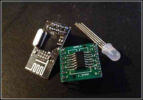
My current project involves an RF circuit (the nRF24l01+) and an RGB LED. But the LED needed some of the same pins that the RF module needs. Can I use this chip?
The Rise and Fall of PWM
The LED is controlled using PWM — pulse-width modulation — a technique for creating an analog signal from code. PWM creates a wave — a rise and a fall.
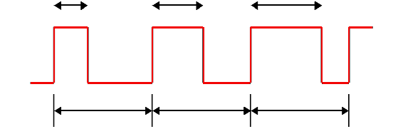
This involves a hardware timer — you toggle a few settings in the chip and it begins counting. When the timer crosses a certain threshold, it can cut the voltage. Change the threshold (the OCR) and you change the length of the wave. So, basically, if I set the OCR longer, I can get a higher voltage. If I set a lower OCR, I get a lower voltage.
I can have the PWM send voltage to the green pin on my RGB LED. And that pin can be either up at 3V (from the two AA batteries powering the ATtiny44a) or it can be down at zero — or PWM can do about anything in between.
My problem, though, was that the SPI pins — which I use to communicate with the RF chip — overlap my second set of PWM pins.
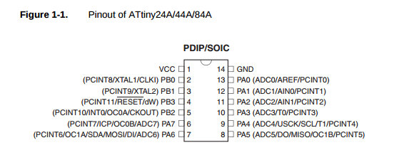
You see — pin 7 has multiple roles. It can be OC1A and it can also be DI. I’m already using its DI mode to communicate with the RF module. The OC1B pin is similarly tied up acting as DO.
I’m already using OC0A and OC0B for my green and blue pins. These pins correspond to TIMER0 — the 8-bit timer used to control those two PWM channels on OC0A and OC0B. To get this timer working, I followed a few steps:
// LED pins
#define  RED_PIN   PA0
#define  GREEN_PIN PB2
#define  BLUE_PIN  PA7
Okay, here are the three pins I want to use. PB2 and PA7 are the TIMER0 pins I was just talking about. I’m going to use another one of the free pins (PA0) for the red pin if I can.
DDRA |= (1<<RED_PIN) | (1<<BLUE_PIN);
DDRB |= (1<<GREEN_PIN);
Obviously I need these pins to be outputs — they are going to be sending out this PWM wave. This code informs the Data Direction Register (DDR) that these pins are outputs. DDRA for PA0 and PA7. DDRB for PB2.
// Configure timer0 for fast PWM on PB2 and PA7.
TCCR0A = 3<<COM0A0 | 3<<COM0B0 // set on compare match, clear at BOTTOM
       | 3<<WGM00; // mode 3: TOP is 0xFF, update at BOTTOM, overflow at MAX
TCCR0B = 0<<WGM02 | 3<<CS00; // Prescaler 0 /64
Alright. Yeah, so these are TIMER0’s PWM settings. We’re turning on mode 3 (fast PWM) and setting the frequency (the line about the prescaler.) I’m not going to go into any detail here. Suffice to say: it’s on.
// Set the green pin to 30% or so.
OCR0A = 0x1F;
// Set the blue pin to almost the max.
OCR0B = 0xFC;
And now I can just use OCR0A and OCR0B to the analog levels I need.
TIMER1, 16-bit is Better, Right?
Most of these AVR chips have multiple timers and the ATtiny44a is no different — TIMER1 is a 16-bit timer with hardware PWM. Somehow I need to use this second timer to power th PWM on my red pin.
I could use software to kind of emulate what the hardware PWM does. Like using delays or something like that. The Make: AVR Programming book mentions using a timer’s interrupt to handcraft a hardware-based PWM.
This is problematic with a 16-bit timer, though. An 8-bit timer maxes out at 255. But a 16-bit timer maxes out at 65535. So it’ll take too long for the timer to overflow. I could lower the prescaler, but — I tried that, it’s still too slow.
Then I stumbled on mode 5. An 8-bit PWM for the 16-bit timer. What I can do is to run the 8-bit PWM on TIMER1 and not hook it up to the actual pin.
// Setup timer1 for handmade PWM on PA0.
TCCR1A = 1<<WGM10; // Fast PWM mode (8-bit)
                   // TOP is 0xFF, update at TOP, overflow at TOP
TCCR1B = 1<<WGM12  // + hi bits
        | 3<<CS10;  // Prescaler /64
Okay, now we have a second PWM that runs at the same speed as our first PWM.
What we’re going to do now is to hijaak the interrupts from TIMER1.
TIMSK1 |= 1<<OCIE1A | 1<<TOIE1;
Good, good. OCIE1A gives us an interrupt that will go off when we hit our threshold — same as OCR0A and OCR0B from earlier.
And TOIE1 supplies an interrupt for when the thing overflows — when it hits 255.
Now we manually change the voltage on the red pin.
ISR(TIM1_COMPA_vect) {
    sbi(PORTA, RED_PIN);
}
ISR(TIM1_OVF_vect) {
    cbi(PORTA, RED_PIN);
}
And we control red. It’s not going to be as fast as pure PWM, but it’s not a software PWM either.
Why Not Use Another Chip?
I probably would have been better off to use the ATtiny2313 (which has PWM channels on separate pins from the SPI used by the RF) but I needed to lower cost as much as possible — 60¢ for the ATtiny44a was just right. This is a project funded by a small afterschool club stipend. I am trying to come up with some alternatives to the Makey Makey — which the kids enjoyed at first, but which alienated at least half of them by the end. So we’re going to play with radio frequencies instead.
I imagine there are better other solutions — probably even for this same chip — but I’m happy with the discovery that the PWM’s interrupts can be messed with. Moving away from Arduino’s analogWrite and toward manipulating registers directly is very freeing — in that I can exploit the chip’s full potential. It does come with the trade off that my code won’t run on another chip without a bunch of renaming — and perhaps rethinking everything.
Whatever the case, understanding the chip’s internals can only help out in the long run.
If you’d like to see the code in its full context, take a look through the Blippydot project.